Dennis La Varenne wrote:It is not of equal distance from either the belly or back except in bows which are symmetrical in cross section.
I should also add that the degree of load taken by the back and belly of a bow DOES relate directly to the distance from the neutral axis to the back and belly surfaces.
On an ELB of conventional Victorian design with a Roman arch belly, an easy way (I hope) that I have found to calculate the neutral plane of an ELB to a reasonable degree of accuracy is to calculate the area of the rectangular section added to the area of the semi-circular section. The square root of that sum will yield an area which can be divided by the width of the rectangular section of the bow to give a depth from the back surface. That depth number is where the neutral layer is situated.
ELB cross section.jpg
Presuming that the drawing above is of an ELB whose width is 40mm x 32mm deep (80% stack) and the red rectangular section is 40mm wide x 10mm deep.
To calculate the area of the black semi-circular section, we use the equation
(Πr^2) ÷ 2, so the area of this semi-circle is -
(22/7 x 20 x 20) ÷ 2 =
628.57mm^2,
The area of the red box section is 40 x 10 =
400mm^2.
Thus the total area of the cross-section is 400 + 628.57 =
1028.57mm^2.
So, √1028.57 =
32.07mm.
Therefore, if the total area of the rectangular cross-section (400) is divided by 32.07, we get 12.47 which is the position of the neutral layer from the back surface as in the illustration in the drawing below.
ELB cross section_2.jpg
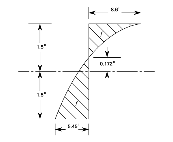
So, the distance from the back surface to the neutral plane is close to 12.5mm and the distance from the belly surface is 16.5 mm, which is 32% greater distance than from the back to the neutral plane. However, because the belly surface of the ELB is also so narrow, the compression load is even greater because that stress is spread over such a narrow width.
If this ELB cross-section had the more conventional Gothic arch shaped belly of the first quarter of the 20th century, the problem of excessive compression and consequent string-follow would be even worse.
Dennis,
It has been some years since I studied any Structural Engineering and this is all straight from memory of broad principles that I was never particularly good with, so I am happy to be corrected in this matter. But, truthfully, you are very close to, or on, the jackpot in your theorising. I believe this is taught differently here in Australia, but in the UK we were taught to use 'Second Moment of Area', which is essentially what you have described.
While balancing proportions of mass is important, the further that mass is from the neutral plane the more internal moments act upon it (and, accordingly, internal forces). Consider an I-Beam - the depth of that beam effects how stiff it is while the thickness of each flange effects how much ultimate load it can hold (among other factors, all other things being equal). For bow making, the width of your limb equates here to the thickness of the flange while the limb cross-section equates to your depth of beam.
If the I-Beam depth is increased, the distance of the centre of mass of each flange from neutral plane increases, thus increasing stiffness but potentially reducing the maximum allowable load, as each flange would now be experiencing greater internal moments upon it. This would be much like building a 1" width bow - no problem if you're using Osage (a strong material) and the bow is only 25lb@28". If you're using Red Oak (a weaker material) and the bow is 50lb@28", it is likely to fail.
If the flanges are thickened, the centre of mass for each section above & below the neutral plane moves away from the centre of mass for the beam as a whole, thus stiffening the beam and increasing the maximum allowable load to the beam. Similarly, if one flange changes material to something stiffer (like bamboo when compared to a standardish timber) the neutral plane will move toward it. However, in this case, the maximum allowable load remains that of the weaker flange.
I've not explained very well there, but here it is in summary -
Centre of Mass multiplied by Distance to Neutral Plane is equal for each section of the bending beam assuming normal, uniform bending (under which bows bend).
For a bow with z-value internal forces, a point 5mm (say, on the very outer edge of a flat bellied bow) from the neutral plane will experience 5mm x z-value internal moments. A point 7.5mm from the neutral plane (say, on the very outer edge of an oval shaped back) would experience 7.5mm x z-value internal moments, an additional 50% loading.
Better explanation found here -
http://www.learneasy.info/MDME/MEMmods/ ... oment.html
Colin has completed his degree more recently and can equate this to Moments of Intertia, which I believe is how the same principle is taught in Australia.
Having just reread your post, I realise I actually skimmed some important details and see that you've pretty much covered exactly what I've written and I am essentially repeating what you've already explained, albeit I am using the I-Beam example. Please accept it as a compliment when I say that that is impressive Engineering for a retired Registered Nurse!
Neil


